| I'm
leaving what I originally posted here, but be sure you
read the updates before you head down this
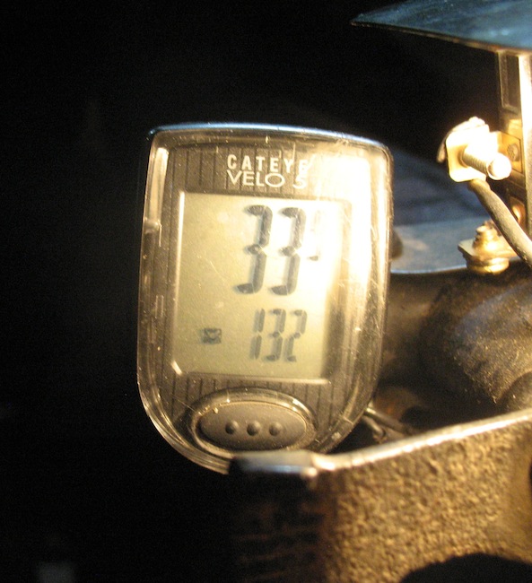
road. (9-26-2022) For the first few years your new Ford came from the factory with a speedometer. But production of the cars became more and more efficient, and they were turned out faster and faster. The speedometer manufacturers couldn't keep up, so Ford quit installing speedometers. You could still buy an aftermarket speedometer for your Ford, but a lot of folks didn't. So today many Model T's have no speedometer. If you want to install one, there are three options. You can buy an original Model T era speedometer, and it will be fine. Its drawback is the price, usually several hundred dollars. Another choice is some sort of GPS device. This has the advantages of being easy to use and less expensive. Its drawback is that it depends on being able to pick up a satellite signal. The third choice is a bicycle speedometer. Its advantages are price (it's least costly of the three options) and accuracy. Its disadvantages are delicate wires and an odometer that goes back to zero when you install a new battery. This page shows installation of a bike speedometer. I have read that some of these go haywire due to interference from nearby ignition coils. That has absolutely NOT been a problem with this speedometer. It's a Cat Eye Velo 5, and I paid less than $25 for it. In fact I've bought it twice. One is on my 1915 runabout and the other is on my 1923 touring. Here's how both are installed: |
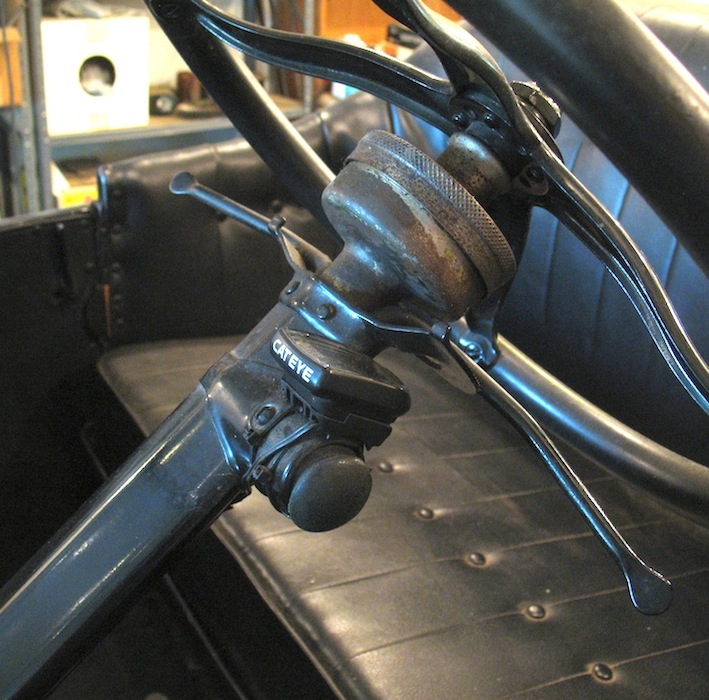
| In cars with a horn button on the steering column, that makes a very handy mounting location. The wire comes up through the tube along with the horn wire, and the computer is mounted over the button with a couple of plastic zip ties. |
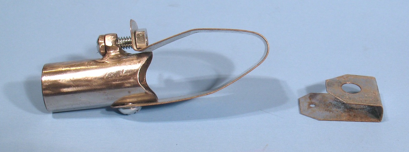
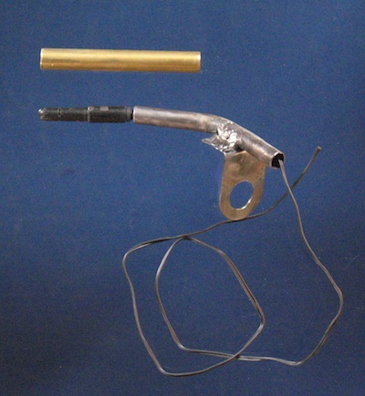
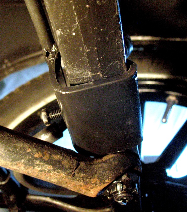
My 1915 has no horn button, so I made this substitute from a piece of 3/4" conduit. The small item to the right is a bracket for attaching the magnet to a wheel.
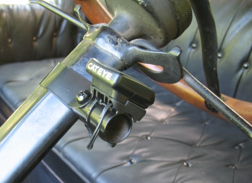
This shows the bracket clamped on the steering column with the speedometer computer zip tied to it.
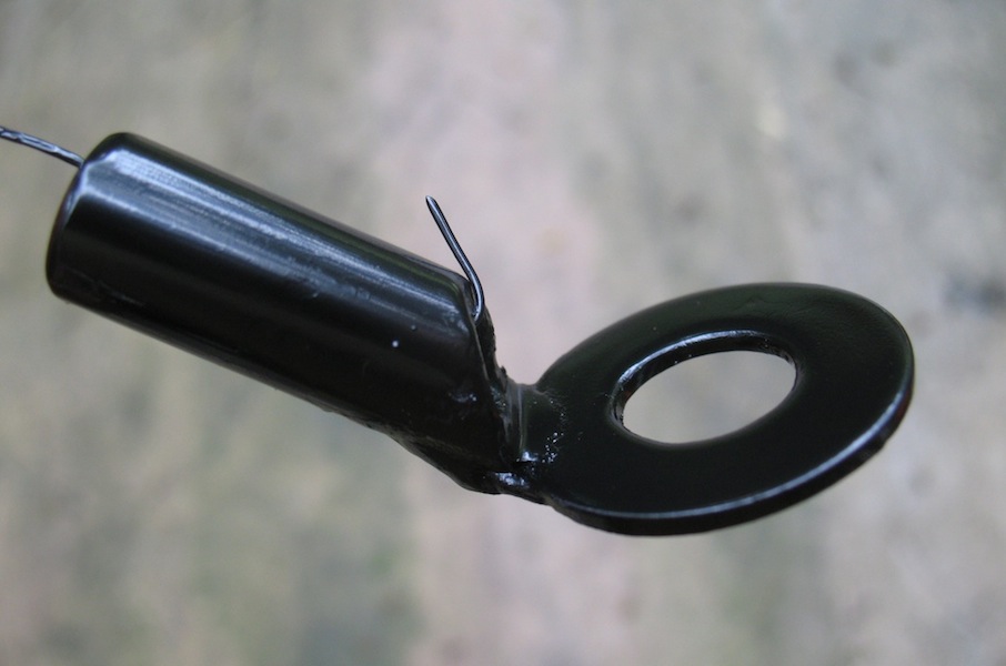
This is the bracket for mounting the sensor. It's just a little piece of pipe welded to a washer.
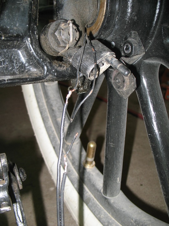
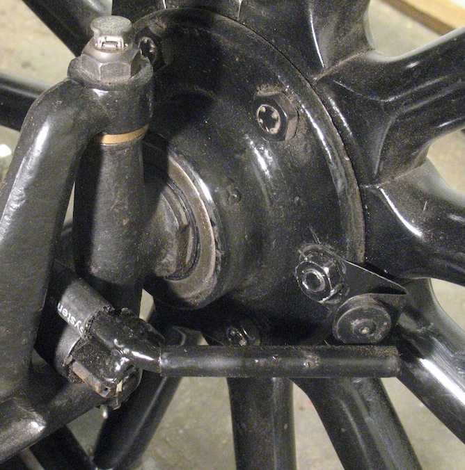
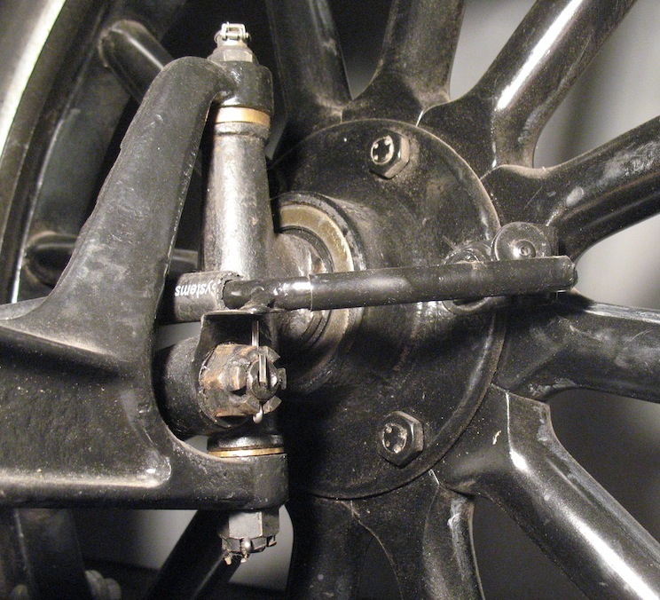
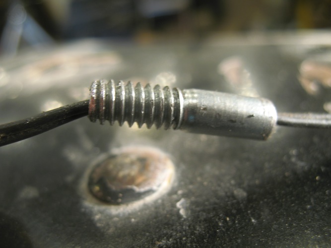
| Here's the bracket attached by the spindle nut. The sensor is mounted on it with Gorilla tape. The magnet is attached to the wheel by a hub nut. Note that the magnet mounting bracket is different from the one in the earlier picture. There have been some changes over the years as I figured out what didn't work very well and what did. This photo also shows the Achilles' heel of this speedometer. The delicate wires are easily damaged by road hazards like gravel kicked up by the wheels. Here you also see that extra wire needs to be spliced in. The wire as it comes with the speedometer is fine for a bike, but isn't long enough for car use. A few feet of speaker wire will solve that. I cover the splices with shrink tubing, which has been cut off here to show the splices and the broken wire. |
My solution to the delicate wire problem is to run it through some 1/4" rubber hose. So far that has worked. I regularly drive on gravel roads, and since adding the hose I've had no more broken wires.
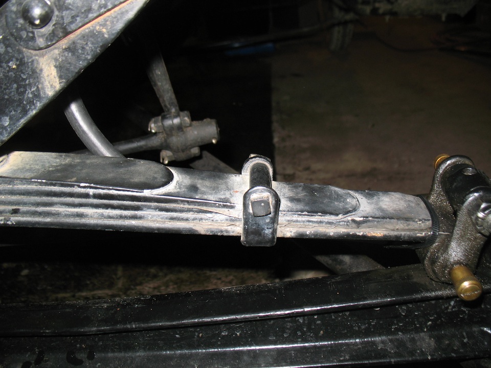
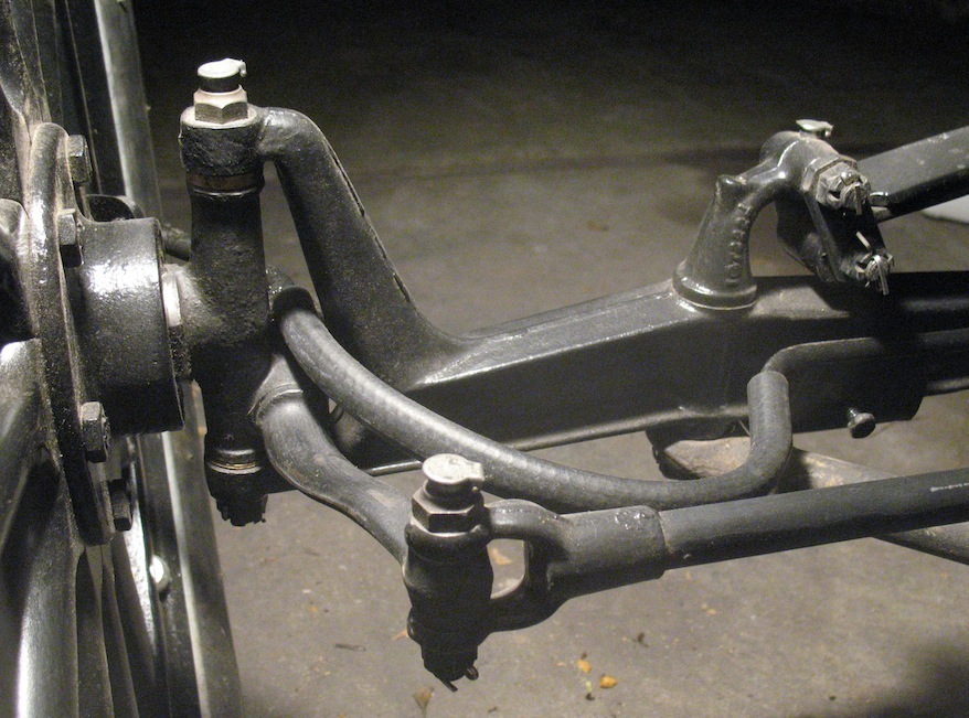
I've attached the hose to the front spring with a zip tie, which you can see next to the shackle. Some people mount the sensor and magnet in the rear of the car instead of using a front wheel. I don't see any reason why that wouldn't work, but I haven't tried it. |
UPDATE: December 8, 2018
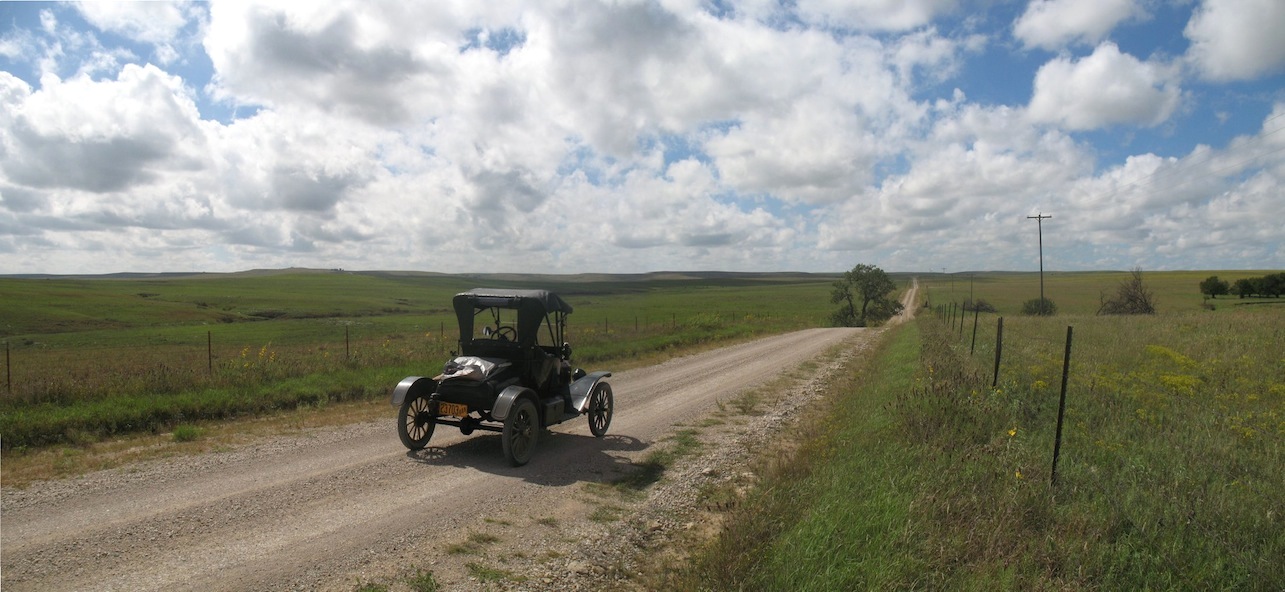
| In September, 2018, I dove my 1915
runabout to Detroit for the Old Car Festival at
Greenfield Village. It was a great trip that I really
enjoyed, and I'll do it again. My estimate of the miles
I drove is about 2870, but I really don't
know exactly how far I went. That's because I had
speedometer/odometer failure a couple of times. The
problem was that although most of the delicate little 20
gauge wires from the sensor were protected inside a
rubber hose, the sensor wouldn't fit inside. That left
it and some of its little wires exposed to road hazards.
So twice those little wires that weren't inside the hose
were damaged by rocks or other debris kicked up by the
wheel. My temporary solution was to wrap the exposed
wires in Gorilla tape, and so far that's working. But lately I've been reinstalling the speedometer on my 1923 touring car after making some front end repairs. Rather than apply the Gorilla tape, I decided to try something more substantial and longer lasting. I expect I'll do the same on the runabout. |
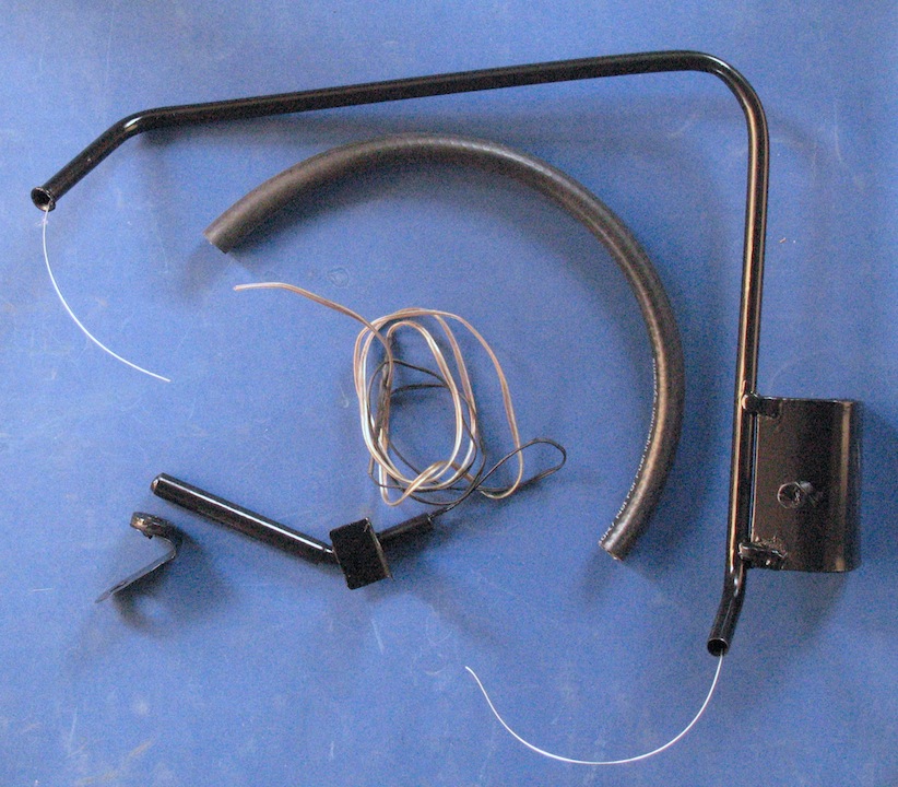
These are the parts
I made. The long tube is 3/8" steel brake line. It's
mounted on a clamp that attaches to the front axle and
is secured by a ¼-20 cap screw. The tricky part
of this operation was welding the thin tubing to the
bracket without burning holes in it. The wire through
the tube is to pull the speedometer wire in when I
mount the parts on the car.
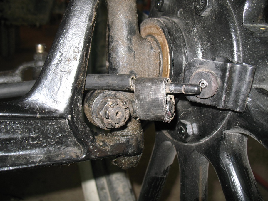
When it came time to install all this gear I found that the steel tubing stuck up too high to allow installation without removing the drag link and connecting rod. It was much simpler to just cut off the top part of the tubing about three inches below the bend and replace that upper end with another piece of hose. Next to the long
tube is a piece of 3/8" fuel hose that will protect
the wires between the two sections of solid tubing.
 Next is the sensor
and cable. The sensor is sealed in a brass tube with
Ultra Black sealant. The 20 gauge wires are spliced to
enough 18 gauge speaker wire to reach up into the
engine compartment. As the photo on the left
shows, a piece of steel tubing is welded to a
mounting bracket that will attach to the spindle. The
non- ferrous brass tubing won't interfere between the
sensor and the magnet, and it just fits over the
sensor and the steel tubing. The final item in the
picture on the right is the magnet attached to its
mounting bracket.
|
 |
 |
 |
 |
 |
 |
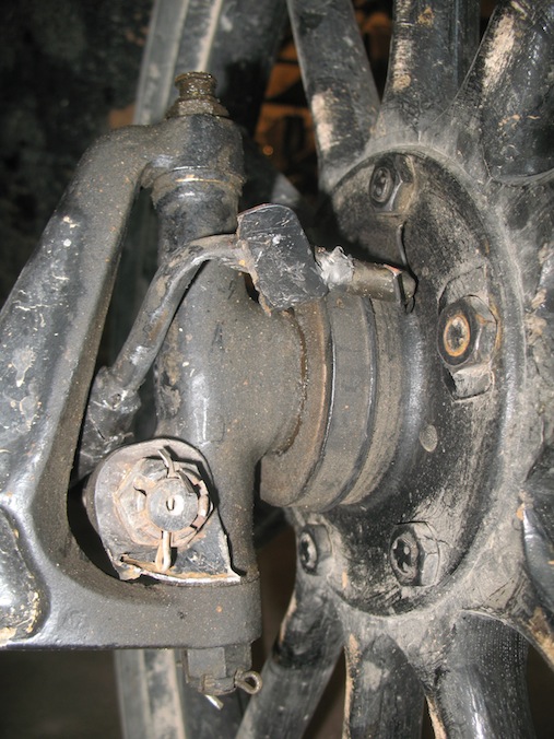
Update: September 26, 2019 As good as all that
fancy hardware looks, recent experience has persuaded
me that there's a better way. Flying rocks and other
road hazards have been just too much for a sensor
mounted on a front wheel. With the latest failure I
found the mounting bracket broken in two and the
sensor completely gone. I decided that I'd try moving
the works to a rear wheel where it might not be
subjected to such abuse. I've lost count of how many
times road hazards have damaged the wiring or knocked
the sensor out of position, so a rear wheel location
can't be any worse.
|
 |
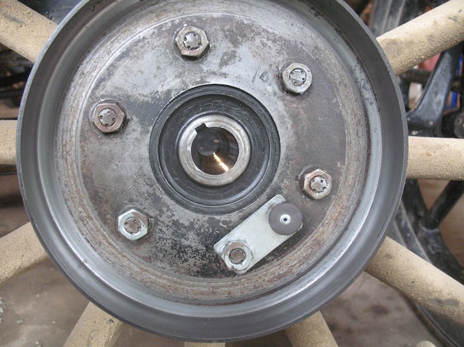 I decided the safest
place for the sensor would be inside the brake drum.
Maybe that will protect it from road hazards. Mounting the magnet inside the drum was easy enough. |
 This location
required a way to get the wires in from outside, so I
made a threaded tube by drilling down the center of a
¼-20 bolt and cutting off the head. Not as easy as it
sounds. I tossed four before I got one right.
|
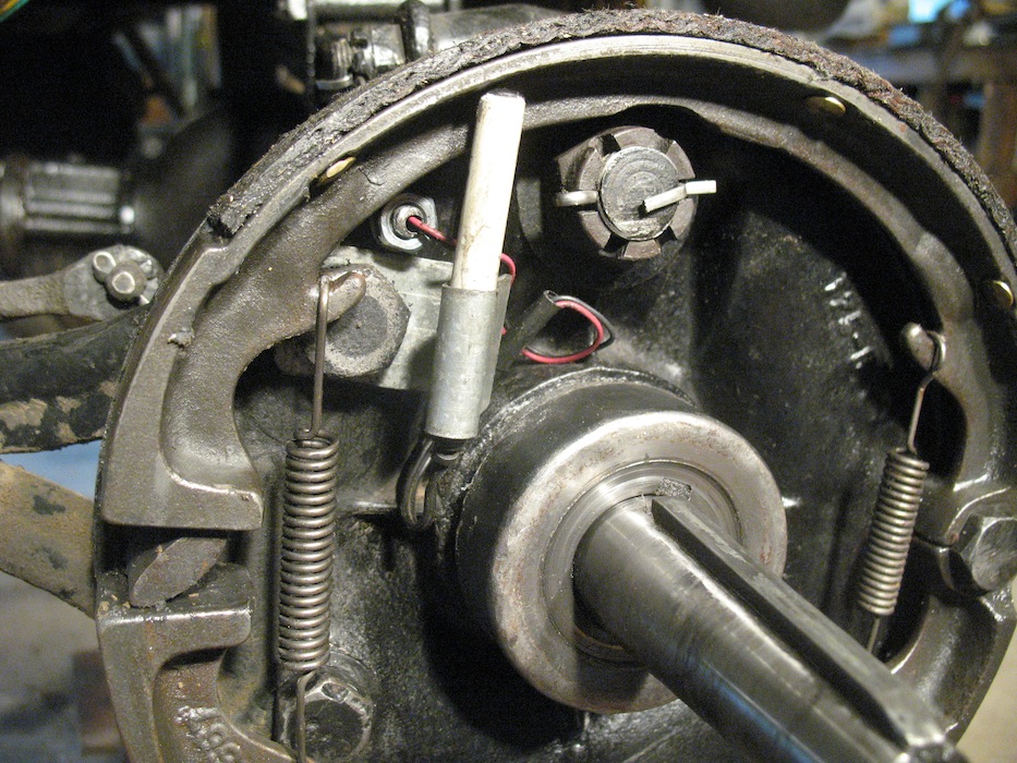 The threaded tube
screws into a hole drilled through the backing plate
to bring in the wires.
The sensor mounting bracket is held by the upper radius rod bolt. |
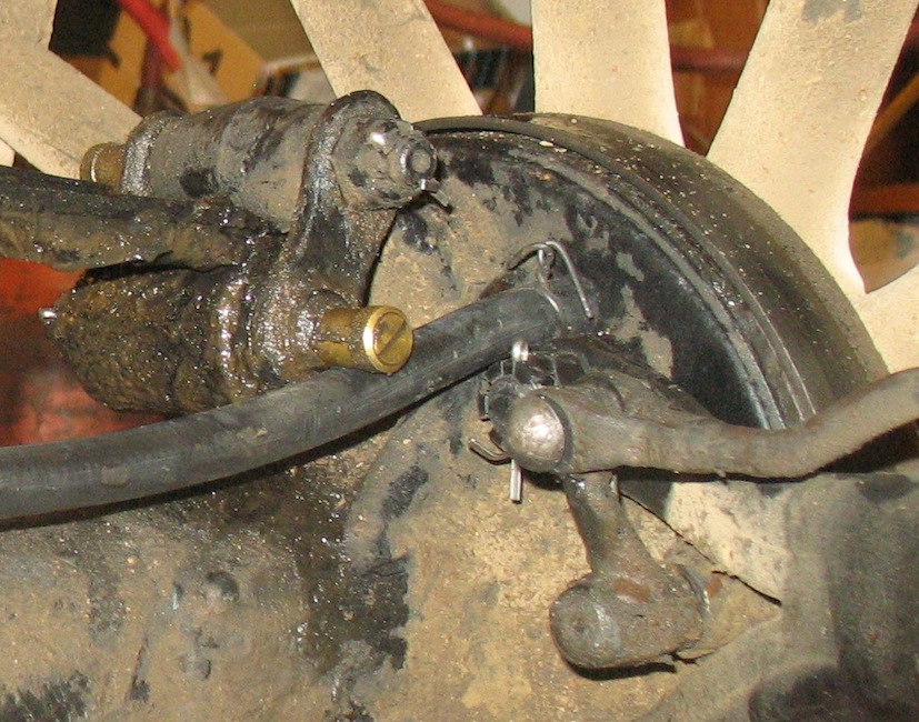 The wires are
protected, I hope, inside a two-foot piece of fuel
hose that goes up into the frame.
The hose is held onto the tube by tightly twisted wire, which is held by the same radius rod bolt that holds the sensor bracket. |
 This arrangement
works very well in the shop with a wheel jacked off
the floor. The real test will be whether it
survives in use out on the road.
|
| Update:
September 26, 2022 I now consider the bicycle speedometer in a Model T a failed experiment. It works wonderfully until it doesn't. I have now made that Detroit trip four times. On the most recent trip, finished a week ago, I didn't even try to use the bike speedometer because I have never had one survive a trip. Even the arrangement with the sensor inside a brake drum failed. You can try it, because it's relatively cheap, but based on my experience I would say you should expect it sooner or later to fail. My 1915 runabout is getting an aftermarket 1916 Stewart Model 100 originally sold for Fords. I will back it up with a GPS device. |